Developed as a solo project for a mechatronics course during the COVID-19 pandemic, this line-following robot represented a comprehensive engineering challenge. With traditional team-based project work disrupted by social distancing requirements, I was responsible for every aspect of the robot’s development—from initial concept and hardware design to software implementation and final testing. The project became an opportunity to demonstrate end-to-end engineering skills, requiring me to simultaneously tackle mechanical design, electronic circuit development, sensor integration, and embedded software programming.
Hardware and Components
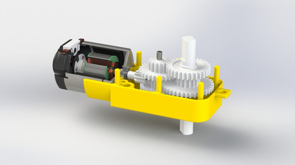
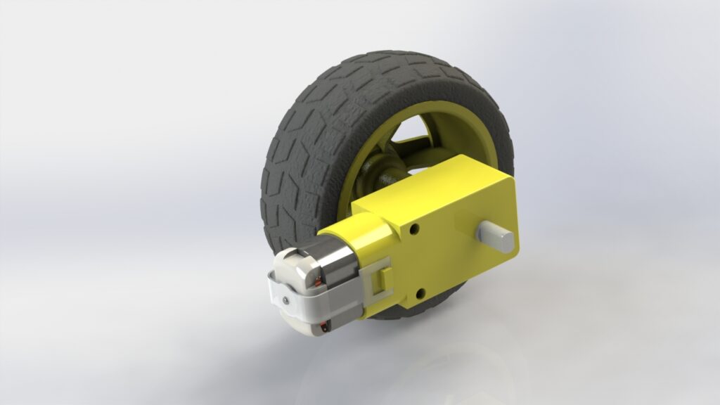
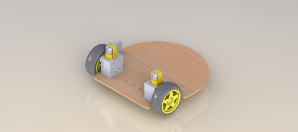
The line-following robot employs a differential drive configuration, a fundamental design that enables precise navigation through asymmetrical wheel speeds. Two 3V-6V DC motors drive individual wheels independently, allowing the robot to turn by rotating one wheel faster or in the opposite direction relative to the other. A ball caster serves as the third point of contact, providing stability and allowing smooth omnidirectional movement while the driven wheels handle primary locomotion.
At the heart of the robot’s intelligence is the PIC24F16KA301 microcontroller, a powerful 16-bit microprocessor that manages sensor inputs, motor controls, and overall navigation logic. The electronic system is built around a custom auxiliary power board that centralizes critical components, including the power switch and sensor mounting points.
Navigation is achieved through three QRD1114 sensors, each consisting of an infrared LED emitter and receiver. Positioned closely to the ground (within 0.5 inches), these sensors detect surface color variations by measuring infrared light reflection. When positioned across the robot’s width, they provide precise line-tracking capabilities by distinguishing between light and dark surfaces.
Motor control is handled by an L298N H-bridge DC motor driver, which enables bidirectional motor rotation and speed control. Custom 3D printed motor brackets provide robust mounting, ensuring precise alignment and minimizing mechanical play. To improve traction, rubber bands were added around the plastic wheels, enhancing the robot’s ability to maintain consistent contact with the surface.
The electrical system is powered by a compact AA battery configuration, with careful consideration given to voltage requirements for both the microcontroller and DC motors. This integrated approach balances computational capability, sensor precision, and mechanical design to create a responsive and adaptive line-following robot.


Software and Programming
The line-following robot’s navigation is powered by a state machine architecture implemented in C for the PIC24F16KA301 microcontroller. At the heart of the design is a sophisticated decision-making system that uses three QRD sensors to detect and respond to line variations in real-time. The robot defines eight distinct states—including forward, various degrees of left and right turns, and a stop state—allowing for nuanced line tracking across different path configurations.
The robot’s state machine leverages pulse-width modulation (PWM) to achieve precise line following by continuously processing sensor inputs and dynamically adjusting motor speeds. By comparing analog sensor readings against a predefined threshold, the system can distinguish between line and non-line surfaces, allowing it to execute corrections—from subtle turns to hard redirections—ensuring smooth and accurate navigation.
