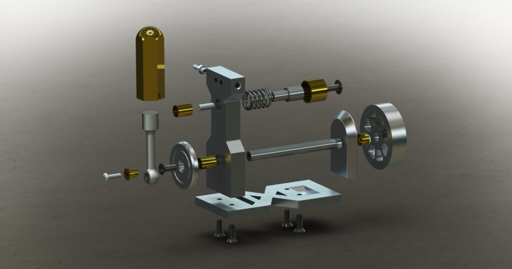
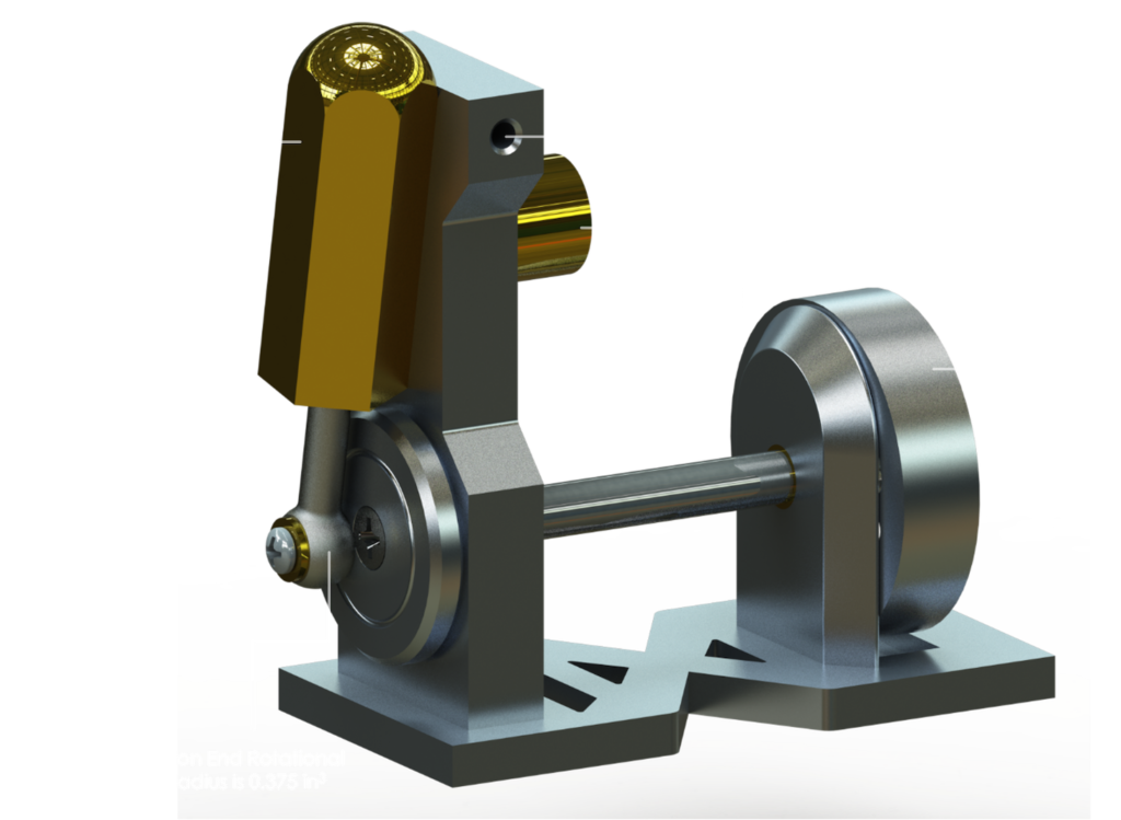
The Pipsqueak Engine is a compact, compressed air-driven mechanism that was developed over the course of two classes: computer aided design (CAD) and manufacturing processes. Its operation relies on a carefully choreographed interaction between key components: a brass cylinder, a piston, a crank wheel, and a flywheel.
Mechanism
Compressed air enters through a nozzle into the main upright, then flows into the brass cylinder. As air pressurizes the chamber, it drives the piston downward, rotating the front crank wheel. This rotational motion is transferred through the crankshaft to the flywheel, which stores and smooths the engine’s mechanical energy through its inertia.
The engine’s design incorporates a pivoting cylinder mechanism that controls air intake and exhaust. As the crank wheel rotates, the cylinder pivots around its central mounting point. This movement strategically misaligns and realigns air intake and exhaust ports. When the intake holes become blocked, the cylinder rotates to expose the outflow port, allowing the compressed air to rush out of the piston cavity just as the piston begins to retract. Once the piston has retracted back into the cylinder, the cylinder rotates back to align with the inflow port, whereupon compressed air enters to drive the piston down and restart the cycle.
Computer Aided Design
The CAD phase of the Pipsqueak Engine project was critical for developing a comprehensive understanding of advanced 3D modeling techniques. Through this process, I focused on three key learning objectives:
- Assembly Modeling: Creating 3D models of individual engine components and demonstrating their mechanical interactions through a comprehensive assembly.
- Motion Analysis: Simulating the engine’s mechanical movement, including piston travel, cylinder rotation, and crankshaft dynamics to validate design feasibility.
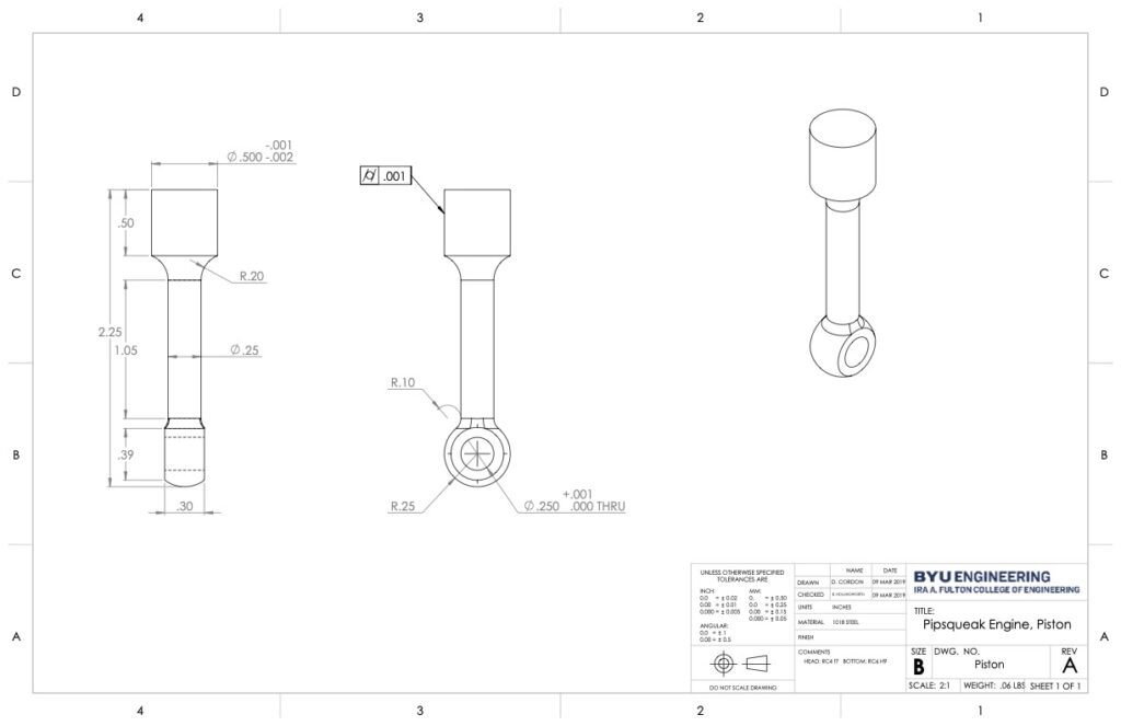
- Geometric Dimensioning and Tolerancing (GD&T): Applying precise tolerancing to ensure component compatibility and defining standardized mechanical relationships.
Manufacturing Processes
The manufacturing class revealed critical insights into production strategies, emphasizing how design must adapt to available processes and production volume. While my initial CAD design was fundamentally sound, practical manufacturing constraints required strategic design modifications. For the Pipsqueak Engine, this meant reconsidering component geometries, material choices, and fabrication methods to align with available equipment and project requirements.
The Pipsqueak Engine’s components were fabricated using an assortment of available manufacturing techniques. The flywheel was produced through sand casting, while the base, uprights, and cylinder were shaped by manual machining. The crankshaft, crank wheel, and spring casing were formed on a lathe, and the piston required a combination of turning and manual machining. Post-processing, including threading and deburring, completed the component fabrication process. Final assembly brought all these components together into a functional compressed air engine.

Demonstration
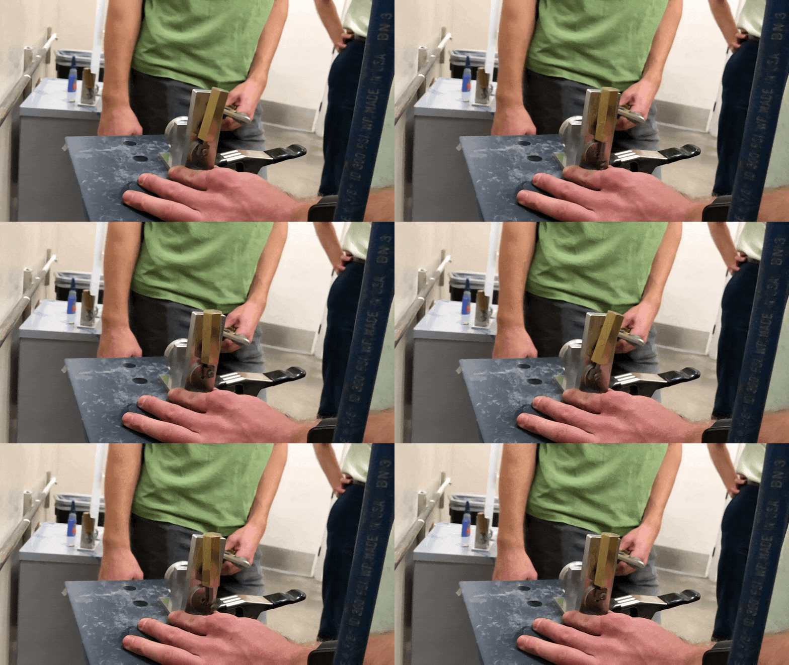
The final results can be viewed here. Below are a .gif image, showing the operation of the Pipsqueak Engine in slow motion, and a video demonstrating a low-pressure test to check the engine’s efficiency at minimal air pressure.
